
Optimizing Brace Forces and Steel Weight
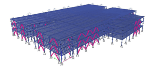
Tectonus worked with Herrick Steel to value engineer a large steel-framed data center development in the Pacific Northwest. The original design used Buckling Restrained Braces (BRBs) as the Seismic Force Resisting System (SFRS) in both principal directions. .
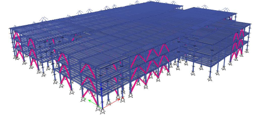
Rather than changing the lateral layout, the study retained the existing building model and braced-bay locations and assessed DMAX braces within the same basic SFRS geometry. The resulting scheme used 64 DMAX braces across 16 braced bays in each direction.
How DMAX changes the structural response
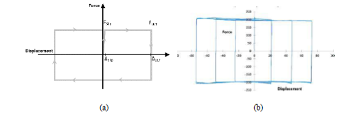 DMAX load deformation curve: (a) Force-deformation behavior, (b)Hysteresis loop from experimental test.
DMAX is a tension-compression steel brace incorporating a passive friction damping mechanism. During an earthquake, energy is dissipated through controlled sliding between clamped friction surfaces. The device response can be tuned to suit the required structural performance, including its initial stiffness and the force at which sliding occurs. The report also describes an external jacket with anti-buckling plates intended to maintain brace stability once sliding begins.
The damping mechanism does not rely on yielding of the brace steel, and the report characterizes DMAX as being free from strain hardening. In engineering terms, the objective is not simply to provide ductility: it is to dissipate energy while maintaining a more controlled force-deformation response. Every DMAX device is also performance tested before shipment against its target load-deformation behavior.
Because of the precise control of DMAX hysteretic performance, demonstrated through prototype and production testing, engineers can be confident in using an overstrength factor (capacity design factor) of 1.15.
Optimizing the braces around the building
The existing ETABS model was modified to incorporate DMAX braces, with brace forces initially estimated from elastic analysis and then optimized against base shear and inter-story drift.
For this comparative study, the DMAX scheme was analyzed using R = 8, consistent with the design basis used for the original BRB scheme. That should not be read as establishing a generally prescribed R value for DMAX; code acceptance needs to be considered for the specific project and approval pathway. The study used modal response spectrum analysis (termed RSA in the report) with the response then checked using nonlinear response-history analysis.
The optimization did not produce the same result in both directions
On the capacity basis used in the report, the X-direction DMAX braces were reduced by approximately 5.6% compared with the BRB scheme. In the Y-direction, the ground-story capacity remained equivalent to the BRB design, while capacity at the upper level was reduced, producing an overall 10.3% reduction.
That is the value of tunability: the brace can be optimized around the response of the building rather than simply substituted at the same nominal capacity.
What happened to drift?
The modal response spectrum analysis produced maximum interstory drifts of approximately 1.2% in the X-direction and 1.3% in the Y-direction. Across the nonlinear response-history analyses, the reported mean drift was approximately 1.9% in both directions. Individual histories produced higher peak values, so the nonlinear result should be understood as a suite mean rather than a statement that every individual response remained below 2%.
That distinction is important. The design question is not whether we can simply reduce brace capacity; it is how far the system can be optimized while still satisfying the project’s governing performance criteria.
40.3% reduction in steel weight within the framing scope compared in the study, equivalent to approximately 365 US tons (331 metric tonnes).
Importantly, the beam and column weights were held constant in that comparison. The reported reduction therefore came from the brace portion of the framing rather than from assumed savings in columns, beams, foundations or other components.
There may be further opportunities
A brace system that can dissipate energy while more tightly controlling maximum force can potentially reduce capacity-design demands on connections, collectors, diaphragms, columns and foundations. But those savings should be demonstrated project-by-project rather than assumed.
That is why we see the greatest value when DMAX is considered early enough for the structural engineer to model and optimize the complete lateral system – as demonstrated in this case study for a private hospital in a New Zealand earthquake zone.
If you would like to understand the DMAX testing and modeling basis in more detail - or have a project you would like us to assess - get in touch with the Tectonus engineering team.